Pad-Mounted Transformer: Technical Guide
What a Pad-Mounted Transformer Is
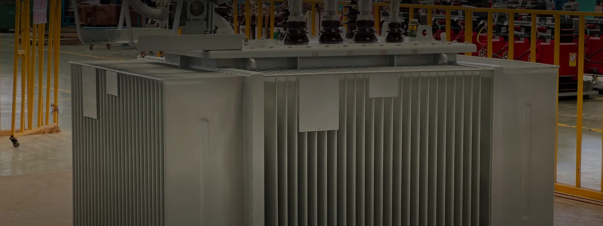
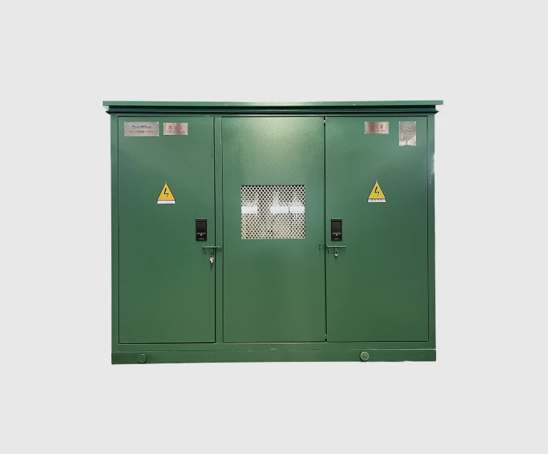
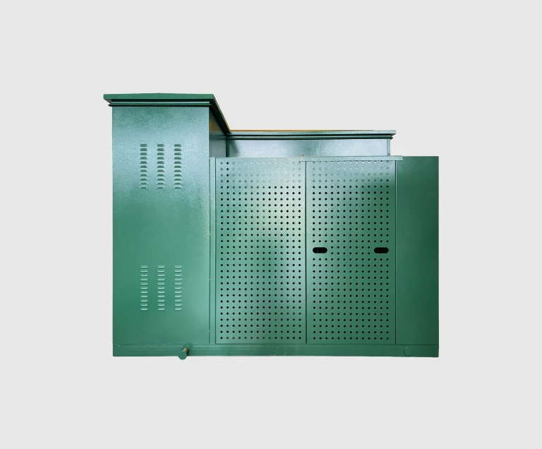
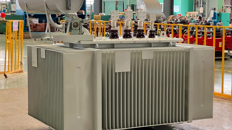
A pad-mounted transformer is a distribution transformer designed to sit outdoors on a concrete pad rather than on a utility pole or in a fenced substation. The defining characteristic is its self-contained, tamper-resistant construction: the transformer tank, the HV primary connections with fuses and switches, the LV secondary connections, and the cooling provisions are all integrated into one steel enclosure with lockable hinged doors on the front. There is no separate switchgear cubicle, no fenced area around the unit, and no exposed live conductors on the outside of the enclosure. The complete unit ships from the factory ready to install — a utility crew sets the transformer on its prepared concrete pad, pulls the HV and LV cables up through the pad and into the front compartment, terminates the cables on the dead-front bushings and LV terminals, locks the compartment, and energizes.
Pad-mounted transformers became the standard for North American suburban distribution in the 1960s and 1970s, replacing the older configuration of pole-mounted transformer fed through a pole-top fuse cutout. The advantages — tamper-resistant security in publicly accessible areas, no overhead conductor clutter, integrated protection and switching — made them the natural choice as residential and commercial developments moved underground. Today essentially all new North American suburban distribution is pad-mounted, and the equipment style has been adopted internationally for applications where the integrated approach makes sense.
ZG Type Designation Explained
Chinese GB standards use a type designation system to encode the pad-mounted transformer's construction, phase count, fluid, conductor, core, and HV connection type. The EverWins ZG-family designation breaks down as follows:
• ZG — Pad-mounted transformer or unitized substation. The product family.
• D or S — Phase count. D = single-phase (Dānxiàng 单相), S = three-phase (Sānxiàng 三相).
• Blank or R — Insulating fluid. Blank = mineral oil (standard), R = nonflammable fluid.
• Blank or B — Coil conductor. Blank = copper wire (standard), B = copper foil.
• Blank or H — Core material. Blank = silicon steel (standard), H = amorphous metal.
• L or R — HV connection type. L = Loop feed (two HV cables, ring main), R = Radial feed (single HV cable, radial distribution).
A complete type designation includes the capacity and voltage after the letter code. So ZGS-L-1000/15 reads as: Pad-mounted, three-phase, mineral oil, copper wire, silicon steel core, loop-feed, 1000 kVA, 15 kV class. ZGD-R-50/12 reads as: Pad-mounted, single-phase, mineral oil, copper wire, silicon steel core, radial-feed, 50 kVA, 12 kV class. The full encoding makes it possible to specify the exact construction in a few characters — useful for utility purchase orders and standardized stock numbering.
Loop Feed vs Radial Feed — Network Topology
The L versus R distinction in the type code describes how the pad-mounted transformer's HV side connects to the upstream distribution network. The choice is driven by the network topology, not by the transformer itself — the underlying core and windings are identical between L and R variants.
Loop feed (L) is the modern standard for new suburban and commercial distribution. The HV side has two cable terminations and a three-position load-break switch — closed-open-grounded for each side of the loop. The transformer is installed in series along a closed ring main cable that loops back to the substation through several other transformers. Under normal operation, the switch is closed on both sides and the transformer can be fed from either direction. If a cable fault occurs on one side of the ring, the utility opens the switch on the faulted side, isolating that cable segment while the transformer continues to be supplied from the healthy side — no service interruption to the loads downstream of the transformer.
Radial feed (R) is the simpler topology used for end-of-line distribution and rural networks. The HV side has one cable termination and one fuse-switch combination. If the upstream feeder faults, the transformer loses power until the fault is cleared and the feeder is restored. Radial feed costs less than loop feed (one less cable termination, simpler switch mechanism) but provides no redundancy against upstream cable faults.
In urban and suburban North American distribution, virtually all new installations are loop-feed because the cost difference is small and the reliability benefit is substantial. Radial feed remains in use for rural single-customer services, end-of-line residential clusters, and small commercial pads where the network is itself radial.
Dead-Front vs Live-Front Bushing Construction
The bushing arrangement on the HV side of a pad-mounted transformer has two distinct styles, with very different operator safety implications. The dead-front design has become the modern standard; the live-front design remains in limited use.
Dead-front construction houses all HV bushings inside the lockable front compartment, with no externally accessible energized parts on the transformer. HV cables enter the pad from below and terminate on the dead-front bushings using elbow connectors — separable insulated connectors rated for full system voltage that engage the bushing through a self-aligning insulating socket. The elbow can be unplugged from the bushing with a hot-stick tool while live, using a load-break or dead-break operation depending on the elbow's rating. With the compartment closed and locked, there is no way for an operator or member of the public to contact a live HV part. This is the design required by most North American utility specifications for residential and commercial installations, and by IEC 62271-202 for prefabricated substations in many international markets.
Live-front construction uses externally mounted HV bushings that protrude through the wall of the front compartment, with the HV cable terminating on an exposed bushing post outside the compartment. The energized cable termination is visible and accessible from outside the locked door. Live-front is cheaper, simpler to install (no elbow connectors), and easier to inspect — but it requires the operator to apply specific safety procedures whenever working near the unit, and it provides no public safety margin if the enclosure is breached. Live-front pad-mounted transformers remain in use mainly in industrial sites with controlled access, where the cost saving and inspection simplicity outweigh the safety considerations.
EverWins ships dead-front as standard. Live-front is available on request where the buyer's project specification requires it — for example, when matching an existing equipment fleet.
North American Utility Standards — ANSI/IEEE C57.12.34
The North American distribution transformer industry is governed by a family of ANSI/IEEE standards under the C57.12.xx series. Three of these directly cover pad-mounted distribution transformers:
• ANSI/IEEE C57.12.34 — Three-phase pad-mounted distribution transformers, 250–5,000 kVA. Specifies construction requirements, dimensional standards, dead-front and live-front bushing arrangements, tap changer configurations, accessory standards, nameplate format, and routine and design test sequences.
• ANSI/IEEE C57.12.38 — Single-phase pad-mounted distribution transformers, 25–167 kVA. The single-phase counterpart, covering residential and small commercial applications.
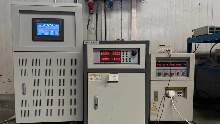
• ANSI/IEEE C57.12.90 — Test code for liquid-immersed distribution, power, and regulating transformers. The detailed test procedure standard referenced by C57.12.34 and C57.12.38.
ANSI/IEEE standards specify the same fundamental transformer physics as IEC 60076 (the international standard), but they differ on dimensional details, accessory configurations, bushing arrangements, and nameplate formats. A transformer designed and manufactured to ANSI/IEEE C57.12.34 will physically fit on a North American utility's standard concrete pad, will accept standard North American elbow connectors on the dead-front bushings, will have the LV bushings spaced for standard North American secondary cable, and will display a nameplate format that North American line crews can read at a glance. EverWins designs and manufactures pad-mounted transformers to these specifications for export to North American utility distribution applications.
How to Specify a Pad-Mounted Transformer
At the quotation stage, confirm the following. Anything you cannot specify, our engineering team can derive from your utility specification or single-line diagram.
1. Phase configuration. Three-phase (ZGS) for commercial, industrial, and three-phase residential loads. Single-phase (ZGD) for North American residential and small commercial.
2. Rated capacity (kVA). Common sizes: single-phase 25, 37.5, 50, 75, 100, 167; three-phase 75, 112.5, 150, 225, 300, 500, 750, 1000, 1500, 2500 kVA.
3. Rated primary voltage. 12.47 kV or 13.8 kV for most North American suburban; 24.94 kV or 34.5 kV for higher-voltage North American distribution; 11 kV or 22 kV or 33 kV for international 50 Hz markets.
4. Rated secondary voltage. 208/120 V wye for North American commercial; 240/120 V split-phase for North American residential; 480/277 V wye for larger North American commercial; 400/230 V wye for international 50 Hz commercial; 11 kV for sub-transmission.
5. HV connection type. Loop feed (L) for ring main networks; Radial feed (R) for radial networks.
6. Bushing arrangement. Dead-front (standard, recommended) or live-front (available on request).
7. Insulating fluid. Mineral oil (standard) or nonflammable fluid (R variant) for fire-restricted installations.
8. Accessories. Surge arresters, fault indicators, fault-passage monitors, remote monitoring radio, secondary metering provisions — specify per the utility specification.
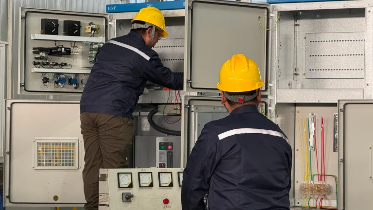
Installation and Maintenance
A pad-mounted transformer is among the lowest-maintenance major electrical equipment in any utility distribution network. The hermetically sealed tank, integrated front compartment, and tamper-resistant lock eliminate most of the maintenance work required by older transformer configurations. Routine maintenance reduces to:
• Annual visual inspection — check enclosure paint, lock condition, oil level indicator, dial thermometer reading, pressure relief device, and external bushing for damage.
• Annual oil sampling — draw a small oil sample for dielectric strength test and moisture content check. Most utilities do this on a rotating schedule rather than every unit every year.
• Periodic infrared thermography — scan the unit under load for hot spots indicating loose terminations or contact problems inside the compartment.
• Surge arrester inspection — confirm the surge arresters have not failed (visible disk discoloration on polymer types).
• Vegetation control — keep the area around the unit clear of vegetation that could impede heat dissipation or animal contact.
Properly specified and maintained, a pad-mounted transformer reliably delivers 25+ years of service. The dominant failure modes are external — vehicle impact damage to the enclosure, vandalism, animal contact through unsealed openings, and external cable termination faults. All four are addressable through facility-level controls and proper installation rather than transformer maintenance.