search
Search

Enter keywords to search for products, blog posts, and more.

English
oil immersed
transformer

Withdrawable Low Voltage
Switchgear (GCK)

Withdrawable Low Voltage Switchgear (GCK Series) — Drawer-Type LV Switchboard and Motor Control Center

Withdrawable Low Voltage Switchgear (GCK Series) — Drawer-Type LV Switchboard and Motor Control Center

GCK Type Withdrawable Drawer-Type Power Distribution Switchgear (PCC) Motor Control Center (MCC) Up to 6300A Up to 50kA Icw Form 3b / Form IEC 61439-2 / GB 7251 Modular Standardized Units

EverWins manufactures withdrawable low voltage switchgear in the GCK series — a modular, drawer-type platform designed for reliable power distribution and motor control. Rated main bus currents extend from 630 A to 6300 A, with short-time withstand current up to 50 kA. Each functional unit — outgoing feeder, motor starter, ACB main breaker, capacitor bank, or measurement panel — is mounted on a steel withdrawable drawer that racks between connected, test, and isolated positions, allowing easy maintenance with withdrawable components without disconnecting cables or de-energizing the rest of the switchboard. The drawer-type construction is the international standard for industrial low voltage switchgear and motor control centers (MCC); the GCK designation under Chinese GB 7251 corresponds to the drawer-type construction class used in markets worldwide, including products marketed under the MNS designation. Designed and manufactured to IEC 61439-2 for industrial plants, commercial buildings, water and wastewater treatment facilities, mining operations, infrastructure projects, and renewable energy balance-of-plant systems.


Service & Delivery

• MOQ: 1 functional unit for standard configurations; project lots quoted as switchboard line-ups

• Lead time: confirmed at quotation, based on number of cabinets, drawer count, and customization scope

• Shipping: FOB, CIF, or DDP terms supported; plywood-case export-grade packaging

• Custom support: single-line diagram review, drawing approval, factory acceptance test (FAT) witness available

• After-sales: technical support via email, phone, or video call; English-speaking engineering team; commissioning guidance

• Warranty: standard manufacturer warranty as detailed in commercial offer

Specifications

ParameterSpecification
Rated Operating Voltage (Ue)380 V / 400 V / 415 V / 660 V / 690 V (50 Hz or 60 Hz)
Rated Insulation Voltage (Ui)Up to 1000 V
Rated Frequency50 Hz or 60 Hz
Rated Main Busbar Current (Ie)630 A / 1250 A / 1600 A / 2000 A / 2500 A / 3150 A / 4000 A / 5000 A / 6300 A
Rated Short-Time Withstand Current (Icw)Up to 50 kA for 1 second
Auxiliary Circuit VoltageAC 220 V; DC 48 V / 110 V / 220 V
Drawer Functional Unit TypesACB main breaker, outgoing feeder (MCCB or fuse-switch), motor starter (with contactor + overload + optional soft starter or VFD), capacitor compensation, measurement
Drawer Position StatesConnected / Test / Isolated, with key interlock against racking under load
Form of Internal SeparationForm 3b / Form 4 per IEC 61439-2 (per project specification)
Enclosure Protection (IP)IP3X standard; IP4X available
Cabinet MaterialCold-rolled steel and aluminum-zinc coated (galvalume) steel
Surface TreatmentPowder coated, colour customizable
Bus System3-phase + N + PE, copper main busbar
Standard Dimensions (W × D × H)600 / 800 / 1000 × 800 / 1000 × 2200 mm
PackingPlywood case, export-grade
StandardsIEC 61439-1; IEC 61439-2; GB 7251.1
Ambient Temperature−5 °C to +40 °C; 24-hour average ≤ +35 °C per IEC 61439-1
Altitude≤ 2,000 m standard per IEC 61439-1
Service Life (design)20+ years with routine maintenance


Withdrawable Low Voltage Switchgear (GCK) Product Range


Drawer Construction and Interchangeability

Every GCK functional unit is built into a standardized steel drawer frame that handles the complete electrical circuit — main contacts on the rear primary disconnects, control circuit on the front secondary plug. The drawer racks into position with a hand crank, and a position indicator on the drawer front shows whether the unit is connected, in test, or fully isolated. The mechanical key interlock prevents racking the drawer in or out while the main breaker is closed, eliminating the most common cause of low voltage arc flash. Identical drawer sizes mean any standard motor starter drawer can be swapped for any other of the same size at any time — a critical advantage in operations where a failed motor starter must be replaced quickly. Spare drawers can be held in inventory and installed in minutes, with the rest of the switchboard remaining live.

• Standardized drawer frames for full interchangeability of same-size units

• Primary disconnect contacts at rear of drawer with auto-shutter when withdrawn

• Secondary control plug at drawer front with independent disconnect

• Three drawer positions: connected, test, isolated

• Mechanical key interlock against racking under load

• Cold-rolled steel and aluminum-zinc coated cabinet panels

• Powder coated finish, colour customizable per project

• Copper main busbar, 3-phase + N + PE configuration


Full Testing per IEC 61439-2

Every GCK switchboard line-up undergoes the IEC 61439-2 routine verification sequence before it leaves the factory. Routine verifications include incorporation of the protective circuit (visual check of PE continuity), power frequency dielectric withstand at 2 × rated insulation voltage plus 1000 V, insulation resistance measurement, and verification of operation. Mechanical operation of every drawer is checked through the full connected-test-isolated sequence, and the key interlock function is verified on every drawer. The complete line-up is pre-assembled at our factory for dimensional check, drawer interchangeability verification across same-size units, and primary and secondary wiring continuity from the main busbar to each drawer's outgoing terminals. Test results are documented in a factory acceptance test (FAT) report supplied with the shipment. Customers may witness the FAT in person or by live video link.


Configured to Your Single-Line Diagram

A low voltage switchboard is defined entirely by the single-line diagram. Number of cabinets, position of the incoming main breaker, location of the bus coupler, type and quantity of outgoing feeder drawers, motor starter ratings for each MCC drawer, capacitor bank sizing — all of these come directly from the SLD. We build to the SLD exactly as specified. Drawer sizes are selected per outgoing rating (1/8 module up to full-size drawers), cabinet width is selected per drawer count (600 mm, 800 mm, or 1000 mm), cable entry direction is set per site layout (top or bottom), and the form of internal separation (Form 3b or Form 4) is chosen per the safety requirement. Tell us your SLD and protection schedule; we configure the line-up to match.

More About everwins

EverWins is a transformer, switchgear and substation manufacturer based in Guangdong, China. With 30 years in the power transmission and distribution industry and a 70,000m² production facility, we supply factory-direct to projects in over 30 countries.

About Us Certifications Solutions

FAQs

What is the difference between fixed (GGD) and withdrawable (GCK) low voltage switchgear?

What is a Motor Control Center (MCC), and how does it differ from a power control center (PCC)?

The difference is how the functional units are mounted. In a GGD fixed-type switchboard, every circuit breaker, contactor, and relay is bolted permanently into the cabinet wiring; any unit replacement requires de-energizing the affected section, disconnecting all wiring, and rebuilding the connections — typically a multi-hour outage. In a GCK withdrawable-type switchboard, each functional unit sits on a steel drawer that racks in and out by hand, with primary and secondary disconnects automatically engaging when the drawer reaches the connected position. A failed motor starter can be replaced in minutes by swapping in a spare drawer of the same size, with no interruption to the rest of the switchboard. GGD is the economical choice where outages are acceptable and the load is simple distribution. GCK is the standard for any installation where uptime matters — industrial plants, water treatment, mining, hospitals, and any facility with motor control loads.

What are the "Forms" of internal separation in IEC 61439-2? 4What is the difference between GCK and MNS switchgear?

A Motor Control Center (MCC) is a withdrawable low voltage switchboard configured specifically for motor control. Each drawer holds the complete starting equipment for one motor — typically a moulded-case circuit breaker for short-circuit protection, a contactor for switching, a thermal overload relay for overload protection, and where applicable a soft starter, VFD, or intelligent motor controller. A typical industrial MCC line-up houses dozens of motor starter drawers, one per motor in the plant. A Power Control Center (PCC), by contrast, is configured for general power distribution — the drawers hold larger circuit breakers or fuse-switch units feeding floor panels, MCCs, and other downstream distribution equipment. The GCK platform supports both configurations on the same cabinet design; what differs is what gets loaded into the drawers.

What is the typical service life of withdrawable low voltage switchgear?

IEC 61439-2 defines five Forms describing how thoroughly the inside of a low voltage switchboard is divided into separate compartments to protect operators and limit fault propagation. Form 1 means no internal separation — everything in one open cabinet. Form 2 separates the busbar from the functional units. Form 3 adds separation between functional units. Form 4 adds separation between the cable terminals of each unit, so a fault on one outgoing cable cannot affect any other circuit in the same cabinet. The "a" or "b" suffix specifies whether the terminals are in the same compartment as their functional unit (a) or in a separate dedicated terminal compartment (b). Form 4b is the highest separation level and is typically specified for critical industrial installations, data centers, and applications with strict safety codes. EverWins GCK is built to Form 3b or Form 4 per project requirement.

Withdrawable Low Voltage Switchgear: Technical Guide

What Withdrawable Low Voltage Switchgear Is

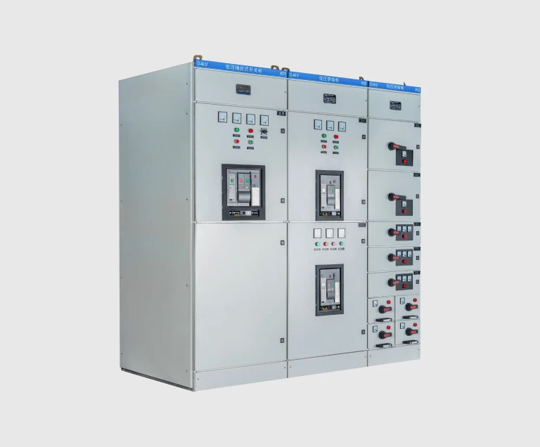
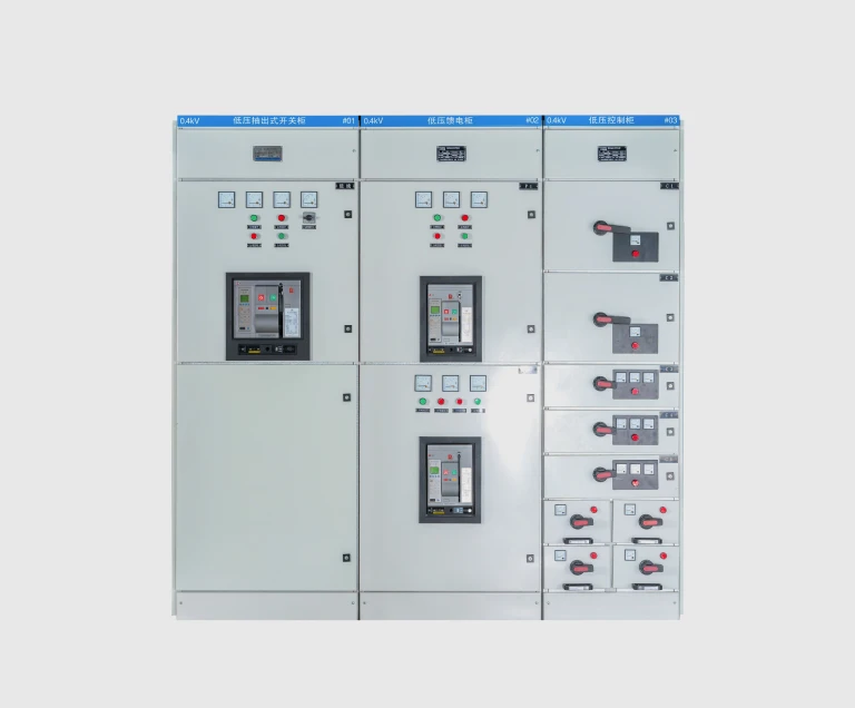
Withdrawable low voltage switchgear is a modular switchboard built around standardized steel drawers. Each drawer holds one complete functional unit — a motor starter, an outgoing feeder breaker, a capacitor bank, or a measurement panel — and racks in and out of the cabinet on rails. When fully racked in, the drawer's rear primary contacts engage the cabinet's fixed busbar contacts and the unit becomes part of the live circuit. When racked out to the test or isolated position, the contacts disengage and the drawer becomes electrically separated from the busbar, with auto-shutters automatically covering the openings to prevent contact with energized parts.

This construction approach is the international standard for industrial low voltage switchgear and motor control centers because it solves the fundamental availability problem of fixed-type switchboards: in a fixed switchboard, replacing a single failed motor starter means de-energizing a section of the switchboard, dismantling the wiring, replacing the equipment, and rewiring — typically a multi-hour outage that may affect adjacent equipment. In a withdrawable switchboard, the failed drawer is racked out, a spare drawer of the same size is racked in, and the motor is back online within minutes — with the rest of the switchboard never losing power.

GCK, MNS, and the IEC 61439-2 Withdrawable Assembly Class

Several type designations refer to drawer-type low voltage switchgear in different markets, and it is worth understanding what they mean.

GCK is the Chinese GB 7251 designation for a drawer-type withdrawable LV switchgear assembly. The letters break down as G (cabinet), C (withdrawable / drawer-type construction), K (switchgear). The standard is closely harmonized with IEC 61439-2 and GCK products are accepted across Asian, Middle Eastern, African, and many European utility specifications.

GCS is a related Chinese GB 7251 designation for a similar drawer-type construction with slightly different drawer dimensions and busbar arrangement. GCK and GCS are commercially treated as equivalent product classes.

MNS is the trade name of a drawer-type LV switchgear system developed by a major European manufacturer in the 1980s. The name became commercially synonymous with the drawer-type construction class, and many international specifications still write "MNS-type" when they mean any drawer-mounted LV switchboard meeting IEC 61439-2 Form 3b or Form 4 separation.

Type-Tested Assembly (TTA) is the IEC 61439-1 designation for any LV switchgear assembly that has been verified through the full type-test sequence of the standard — temperature rise, dielectric withstand, short-circuit withstand, protection against electric shock, mechanical operation, and others. GCK switchgear is built to this standard and verified through the IEC 61439-2 routine test sequence on every line-up.

In practical terms, GCK, MNS, and similar drawer-type designations describe the same construction class with different product names. The functional behavior — three drawer positions, key interlocking, primary disconnects with auto-shutters, type-tested busbar — is the same.

The Three Drawer Positions and Why They Matter

Every GCK drawer has three defined positions, with a hand crank or motorized racking mechanism moving the drawer between them. The position indicator on the drawer front shows which state the unit is in.

Connected position — the drawer is fully racked in. Primary contacts at the rear engage the cabinet's fixed busbar contacts, secondary contacts at the front engage the control wiring plug, and the unit is part of the live circuit.

Test position — the drawer is partially racked out. Primary contacts at the rear are physically separated from the busbar (the drawer cannot pass current to the motor or outgoing cable), but the secondary control contacts at the front remain engaged. This position lets a technician test the control circuit — close the contactor, verify relay logic, exercise the overload trip — without ever putting the motor or outgoing circuit at risk of energization.

Isolated position — the drawer is fully racked out. Both primary and secondary contacts are disengaged, the auto-shutters have closed across the busbar openings, and the drawer is completely electrically separated from the rest of the switchboard. In this state the drawer can be safely withdrawn from its compartment for inspection, contact maintenance, or replacement.

The position indicator is interlocked with the cabinet door and the racking mechanism, so the operator cannot perform an unsafe sequence — for example, racking the drawer in or out while the main breaker is closed under load. This eliminates the most common cause of low voltage arc flash incidents.

Forms of Internal Separation — Form 1 Through Form 4b

IEC 61439-2 defines five Forms of internal separation that describe how thoroughly the inside of a low voltage switchboard is partitioned. The higher the Form, the more isolated each functional unit is from its neighbors, and the better the protection against fault propagation, accidental contact during live maintenance, and operator error.

• Form 1 — no internal separation. The busbar, functional units, and cable terminals all share a single open cabinet interior.

• Form 2 — busbar separated from functional units by a metal or insulating barrier.

• Form 3 — busbar separated from functional units, and functional units separated from each other.

• Form 4 — busbar, functional units, and cable terminals of each functional unit all separated from each other.

The "a" or "b" suffix specifies the terminal arrangement. In Form 3a or 4a, the outgoing cable terminals sit in the same compartment as their functional unit. In Form 3b or 4b, the terminals are in a separate dedicated terminal compartment, which allows cable work to be performed safely on one circuit while the rest of the switchboard remains energized. Form 4b is the highest separation level commonly specified and is required by many industrial specifications, data center standards, and high-availability infrastructure projects. EverWins GCK is built to Form 3b or Form 4 per project requirement.

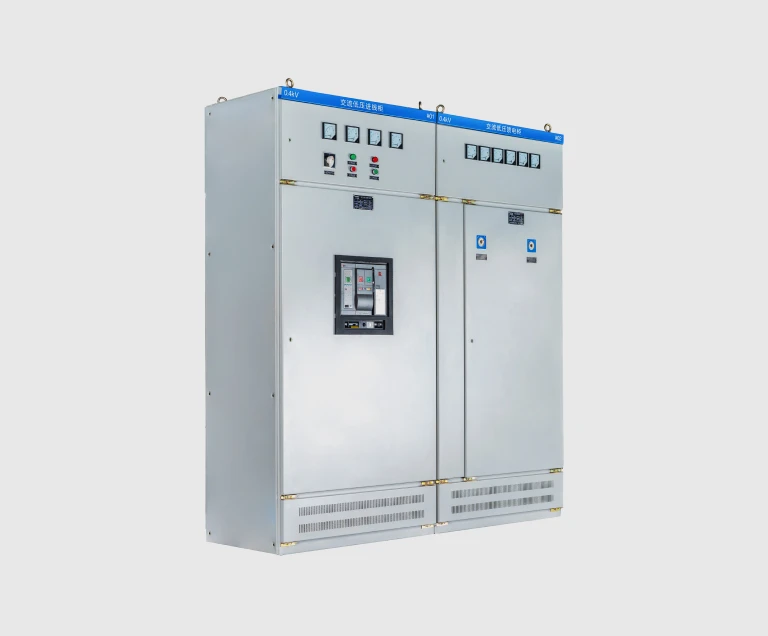
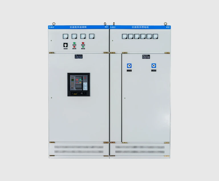
Power Distribution vs Motor Control — Two Configurations of the Same Platform

A GCK switchboard can be configured for two main applications without changing the underlying cabinet structure. The cabinet, busbar, drawer mechanism, and interlock system are identical; the difference is the function loaded into each drawer.

Power Distribution (PCC) configuration:

• Incoming ACB main breaker on a withdrawable drawer, typically 1600 A to 6300 A

• Bus coupler (optional) for two-section operation

• Outgoing feeder drawers with MCCB or fuse-switch units feeding downstream sub-distribution

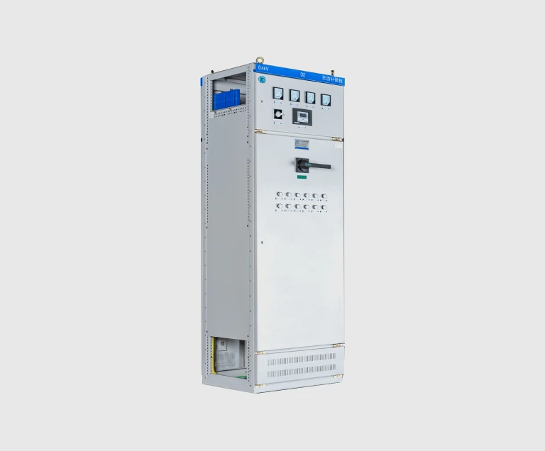
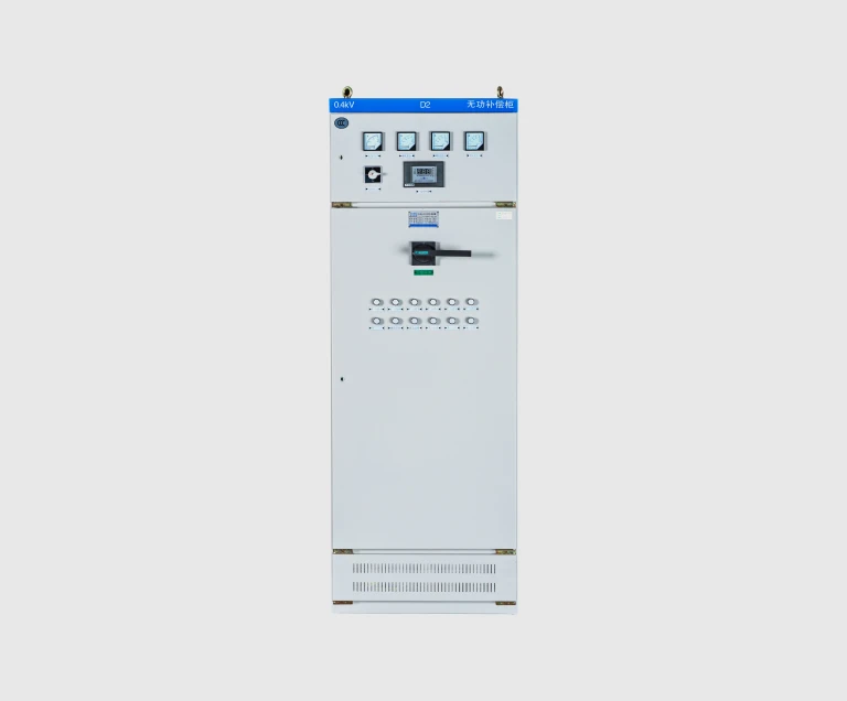
• Capacitor bank drawers for power factor correction

• Measurement and metering panel

Motor Control Center (MCC) configuration:

• ACB main breaker drawer at the incoming side

• Multiple motor starter drawers, one per motor — each containing MCCB + contactor + thermal overload, plus optional soft starter, VFD, or intelligent motor controller

• Drawer size selected per motor rating: 1/8 module for motors below 7.5 kW, larger modules for larger motors

• Control circuit may include PLC, smart relays, or fieldbus interfaces for plant automation integration

Many industrial sites end up with a mix — a Power Distribution line-up at the incoming, with one or more MCC line-ups downstream serving the motor loads in each process area. The GCK platform handles both seamlessly.

How to Specify Withdrawable Low Voltage Switchgear

At the quotation stage, confirm the following. Anything you cannot specify, our engineering team can derive from your single-line diagram and load schedule.

1. Rated operating voltage. 400 V is most common globally; 690 V is used for high-power motor loads in mining and heavy industry.

2. Rated main busbar current. Set by the largest continuous current flowing through the bus, with margin for future growth. Common values: 1600 A, 2500 A, 4000 A; up to 6300 A for the largest substations.

3. Rated short-time withstand current. From the upstream fault-level study, typically the transformer secondary short-circuit current. Up to 50 kA for 1 second covers most distribution-level installations.

4. Form of internal separation. Form 3b is the practical minimum for industrial use; Form 4 or Form 4b is specified where strict safety codes or high-availability requirements apply.

5. Number and type of drawers. List by function: ACB main, bus coupler, outgoing feeders with MCCB ratings, motor starter drawers with motor kW ratings, capacitor banks with kVAR ratings, measurement units.

6. Cable entry direction. Top entry or bottom entry, set by the site cable trench or cable tray layout.

7. Auxiliary supplies. Control voltage (commonly 220 V AC or 110 V DC) and source.

8. Intelligence requirements. Smart motor controllers, Modbus or PROFIBUS fieldbus, integration with plant SCADA or building management system.

Installation and Maintenance

Withdrawable low voltage switchgear is among the most maintenance-friendly electrical equipment in any industrial facility, precisely because of the drawer-type construction. Routine maintenance is:

• Annual visual inspection — check cabinet doors, drawer mechanisms, position indicators, busbar joints visible through inspection windows, and cable terminations for signs of overheating or loosening.

• Thermal imaging under load — scan all busbar joints, ACB contacts, and drawer primary disconnects every 6 to 12 months. Hot spots indicate loose connections that can be tightened during the next planned outage.

• Drawer exercise — drawers that have not been racked for extended periods should be exercised periodically (racked in and out) to keep the mechanism free and the contact wipers cleaning the busbar contacts.

• Contactor and relay testing — motor starter drawers with frequently-operated contactors should be inspected for contact erosion at intervals proportional to operating frequency.

• Insulation resistance check during major outages — verify the busbar and drawer insulation is in good condition.

With this routine, a properly specified GCK switchboard reliably reaches 20 to 25 years of service. The main shell, busbar, and drawer mechanism typically continue in service well beyond that, with individual drawers replaced as they age out — one of the structural advantages of the withdrawable design.