Compact Substation: Technical Guide
What a Compact Substation Is
A compact substation, also called a prefabricated substation, packaged substation, kiosk substation, secondary substation, or compact secondary substation depending on regional preference, is a complete medium voltage to low voltage distribution substation built and tested in a factory, then delivered to site as a single unit. The international standard governing compact substations is IEC 62271-202, which specifies the construction, testing, and rating requirements for high-voltage/low-voltage prefabricated substations rated up to and including 52 kV on the high voltage side and 1000 V on the low voltage side.
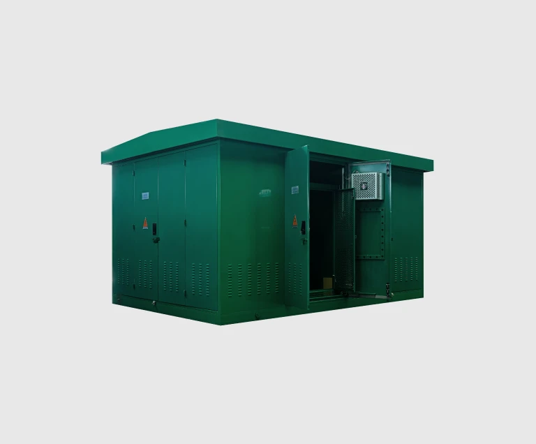
The defining characteristic of a compact substation is its three-compartment architecture: HV switchgear, transformer, and LV switchgear all housed in a single enclosure, with each compartment physically and electrically separated from the others. This architecture is fundamentally different from older substation design, where each piece of equipment occupied a separate room or zone within a brick-built building. The factory-built approach delivers three concrete benefits: faster site deployment, lower total installed cost, and consistent quality because every unit is type-tested and routine-tested as an integrated system rather than assembled from separate parts on site.
The Three-Compartment Architecture
Every compact substation, regardless of regional style, follows the three-compartment architecture. Understanding what sits in each compartment is the foundation for specifying the unit correctly.
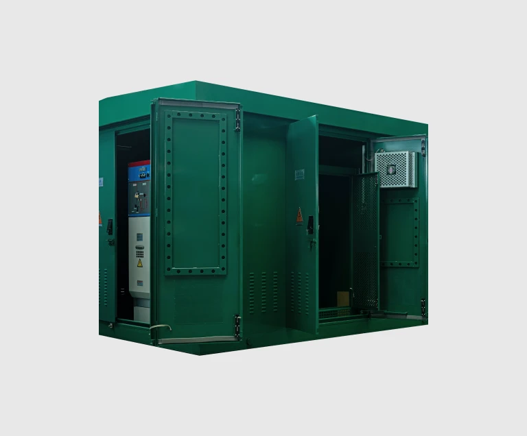
High Voltage Compartment. Contains the incoming HV cable termination, the medium voltage switchgear (typically a ring main unit with SF6 or solid insulation in modern designs), and the HV protection — load break switches, fuse-switch combinations, or vacuum circuit breakers depending on the application. The HV compartment also houses the surge arresters that protect downstream equipment from lightning and switching transients on the primary network.
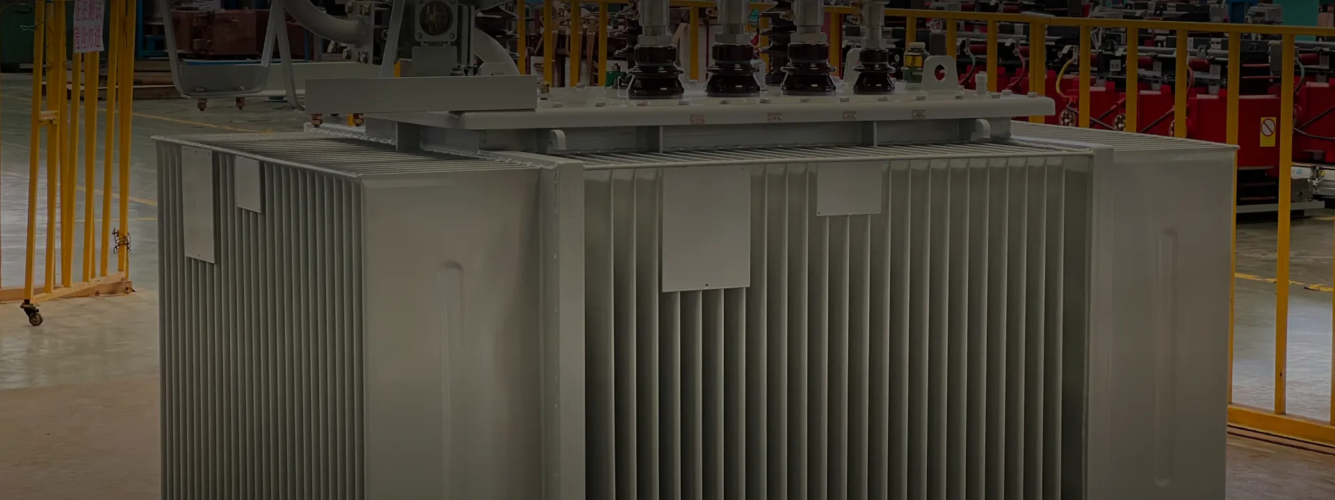
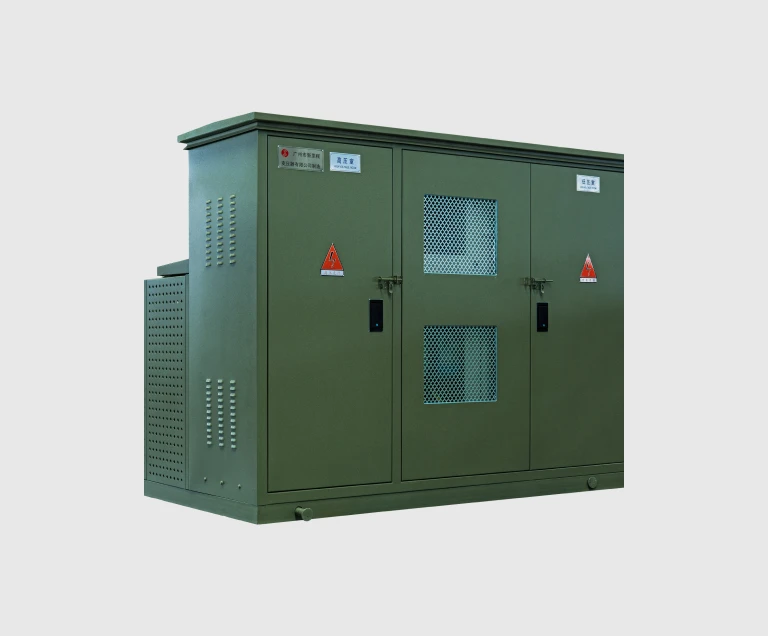
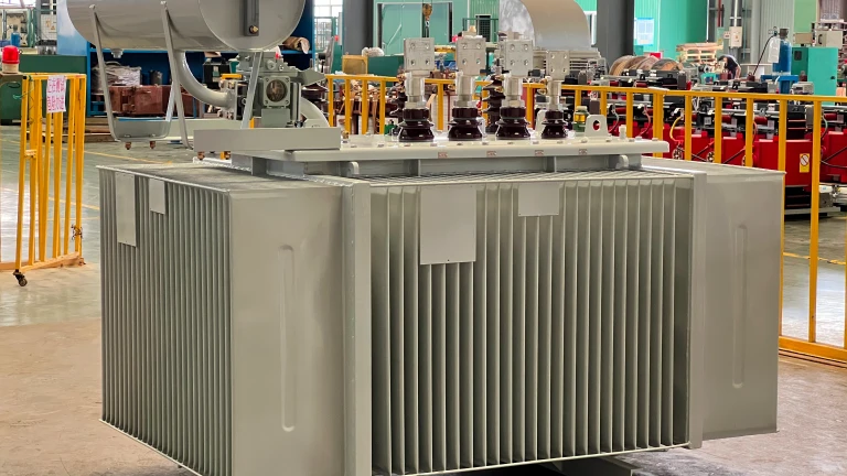
Transformer Compartment. Contains the distribution transformer that steps the medium voltage down to the LV utilization voltage. In European-style compact substations, the transformer is typically housed inside the main enclosure with ventilation provisions sized for the rated capacity. In the YBM-3 variant, the transformer is mounted externally next to the main enclosure, which improves cooling and accommodates larger ratings. The transformer compartment is separated from the HV and LV compartments by metal partitions to contain any transformer fault.
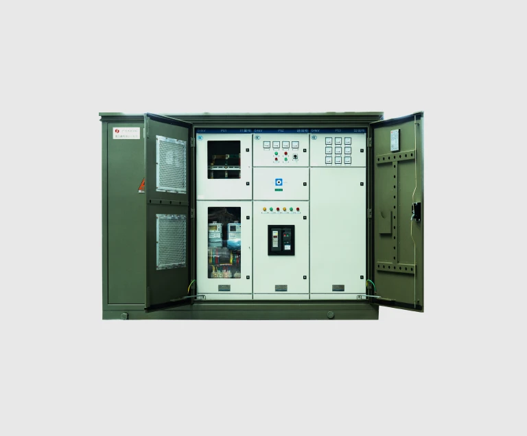
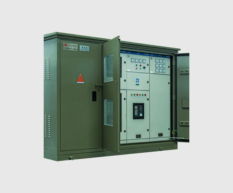
Low Voltage Compartment. Contains the main LV switchboard with the incoming main breaker (typically an air circuit breaker rated for the transformer's full secondary current), outgoing feeder protection (moulded-case circuit breakers or fuse-switches for each downstream circuit), metering and protection relays, and where required, capacitor banks for power factor correction. The LV compartment is the operator's primary interface with the substation — most routine switching, metering reads, and outgoing circuit maintenance happen here.
European vs American — Two Styles of Compact Substation
Compact substations come in two architectural families, each developed for the distribution network practice of its origin region.
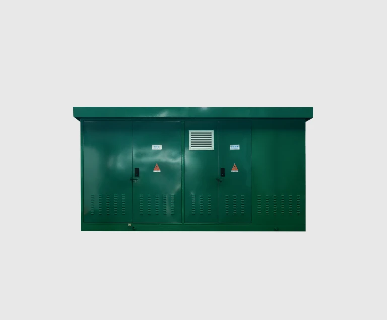
European-style is the integrated three-compartment enclosure described above — HV switchgear, transformer, and LV switchgear all inside one walk-around enclosure with lockable access doors on each side. This style developed in dense European urban networks where compact substations had to fit on small sites with restricted vehicle access, and where ring main HV switchgear was the standard distribution architecture. The European style dominates globally — it is used across Europe, China, the Middle East, Africa, parts of Latin America, and Southeast Asia.
American-style is a fundamentally different concept. The transformer itself is mounted directly on a concrete pad, with HV cables terminating in a front-accessed compartment integrated into the transformer (not a separate switchgear cubicle), and LV connections made from LV bushings at the rear or side of the transformer to a separate LV panel. There is no surrounding enclosure beyond the transformer's own tank and front compartment. This style developed in North American suburban distribution where radial-feed networks (rather than ring main) are standard, and where the simplicity of a self-contained pad-mounted unit serves the lower complexity of those networks.
The choice between European and American style is driven primarily by network topology and local utility practice. For projects in markets that historically use one style (e.g., most non-North American markets use European; North America uses American), the local choice usually dictates. For projects in markets that have used both, the European style is preferred where the substation includes multiple HV feeders, ring main topology, or substantial LV protection complexity; the American style is preferred where a single radial HV feed simplifies the design.
YBM Type Designation and Enclosure Variants
Chinese standards use a type code system to encode the compact substation's installation environment, structural variant, and voltage rating. The EverWins YBM designation breaks down as follows:
• Y — Pre-installed transformer substation (预装式变电站). Indicates the unit is delivered as a factory-built, fully assembled substation.
• B — Installation site: B-O for outdoor (室外), B-I for indoor (室内). Most YBM units are outdoor-rated; indoor-rated units are used where the substation sits inside an existing building or industrial structure that provides weather protection.
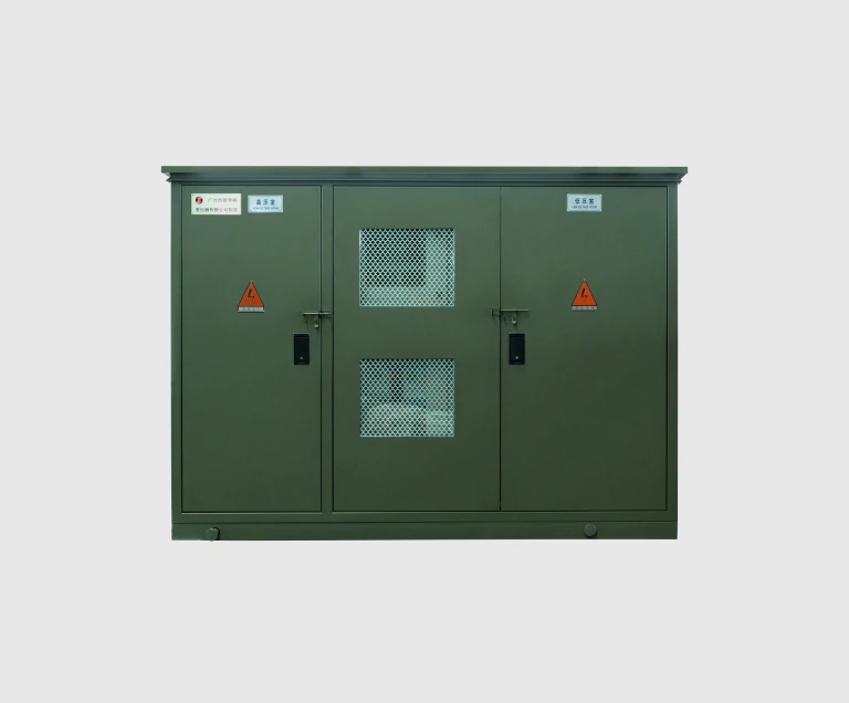
• M — Serial number / structural variant: M-1 for laminated composite enclosure, M-2 for composite + stainless steel cladding, M-3 for steel plate enclosure with externally-mounted transformer.
After the YBM code, two numerical values follow: transformer rated capacity in kVA, and rated voltage on the HV side in kV. So a unit labeled YBM-1-1000/12 is a laminated composite outdoor compact substation with a 1000 kVA transformer at 12 kV class. This naming convention is consistent across Chinese compact substation manufacturers and aligns with the IEC 62271-202 international standard for prefabricated substations.
How a Compact Substation Connects to the Grid
A compact substation sits at the boundary between the medium voltage distribution network and the low voltage utilization network. Understanding how it connects on each side is the foundation for sizing the HV switchgear and LV switchboard correctly.
On the high voltage side, the substation is fed from the medium voltage distribution cable network. The most common HV configuration is the ring main unit (RMU) — two HV cables enter the substation through cable feeder units, allowing the substation to be fed from either direction of the ring. A third internal switch protects the transformer through a fuse-switch combination or a vacuum circuit breaker. This topology means that a cable fault on one side of the ring does not interrupt the substation; the affected cable is isolated and the substation continues to feed from the healthy side.
On the low voltage side, the substation's LV main breaker (typically an air circuit breaker rated for the transformer's full secondary current) connects to the LV main busbar inside the LV compartment. Outgoing feeders branch off the busbar through moulded-case circuit breakers or fuse-switches, each feeding one downstream circuit — a building's LV panel, an outdoor lighting feeder, an industrial process panel. Larger LV installations may include sub-distribution panels downstream, with the compact substation feeding only a few large outgoing circuits.
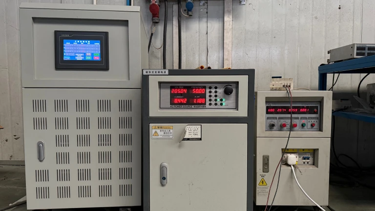
Protection coordination between the HV and LV protection is set during commissioning. The transformer fuses or HV circuit breaker provide last-line protection against transformer faults and downstream LV faults that the LV protection fails to clear; the LV main breaker and feeder protection clear normal downstream faults selectively without operating the upstream HV protection. Proper coordination is essential for network selectivity and is verified at the FAT before shipment.
How to Specify a Compact Substation
At the quotation stage, confirm the following parameters. Anything you cannot specify, our engineering team can derive from your single-line diagram, load schedule, and the local utility specification.
1. Transformer rated capacity (kVA). The dominant sizing parameter. Set by total connected LV load × diversity factor + future growth allowance.
2. Rated voltages. HV primary (typically 11, 22, 33, or 35 kV per the local distribution system) and LV secondary (typically 0.4 kV in 50 Hz markets, 0.48 kV in 60 Hz markets).
3. Transformer vector group and impedance. Dyn11 is the international default; impedance voltage 4% or 6% is typical for distribution duty.
4. HV switchgear configuration. Number of HV feeders (typically two for ring main, one for radial), protection type (fuse-switch versus circuit breaker), and surge arrester provision.
5. LV switchboard configuration. Main breaker rating, number and rating of outgoing feeders, capacitor bank requirement, metering provisions.
6. Enclosure variant. YBM-1 for general deployment, YBM-2 for coastal/polluted/vandal-exposed sites, YBM-3 for hot climate or larger transformer applications.
7. Local utility specification. If the local utility (national power authority, distribution system operator) has a specific compact substation specification, supply the document; we configure to it.
8. Site conditions. Altitude (derating above 1,000 m), ambient temperature range, pollution level, seismic requirements if applicable.
Installation and Maintenance
A compact substation is among the lowest-maintenance major electrical equipment in any distribution network, because the factory-built, sealed-compartment design eliminates most of the field maintenance work that brick-built substations require. Routine maintenance reduces to:
• Annual visual inspection of the enclosure — check for paint or coating damage, water ingress, vandalism, and surrounding vegetation that could block ventilation airflow.
• Annual transformer oil dielectric strength test (for oil-immersed transformer compartments) and visual leak check around the transformer tank and bushings.
• Three to five-yearly thermal imaging of HV and LV bus connections, transformer bushings, and busbar joints under load — catches loose terminations before they fail.
• Mechanical operation verification of the HV switchgear interlock chain and LV main breaker — every one to two years.
• Surge arrester inspection — confirm arresters have not failed (visible disk discoloration on polymer types).
• Cable termination inspection during scheduled outages — check for moisture ingress and physical damage at HV and LV terminations.
With this routine maintenance, a properly specified and deployed YBM compact substation reliably delivers 25 to 30 years of service. The main failure modes are environmental — corrosion of the enclosure in coastal sites without proper variant selection, internal moisture ingress from a damaged seal or unblocked drain, and overloading from undersized initial capacity selection. All three are preventable through correct specification at order stage.