Oil Immersed Transformer: Technical Guide
How an Oil Immersed Transformer Works
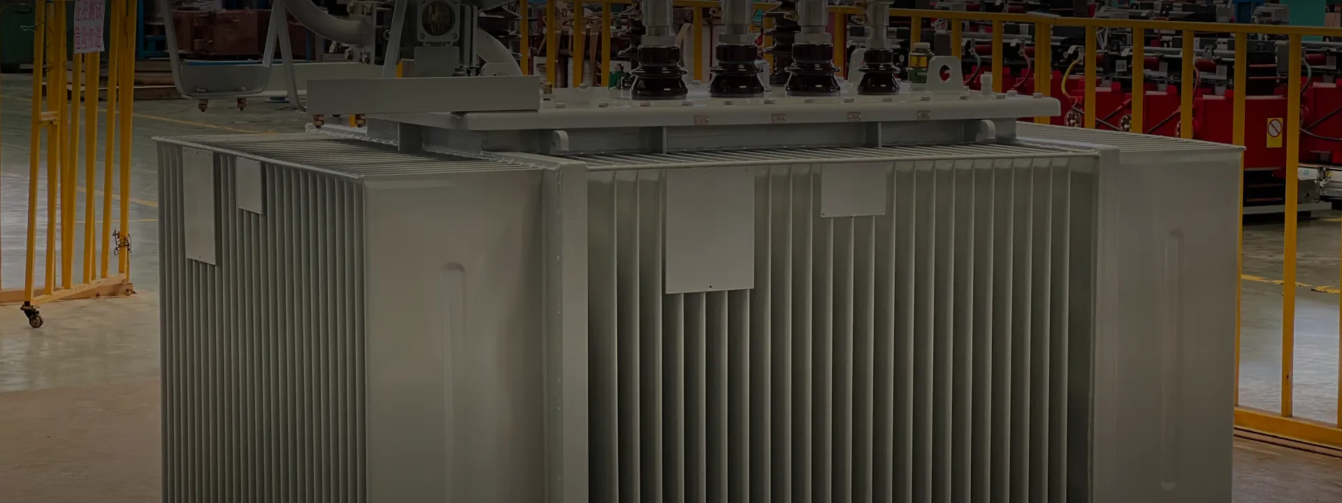
An oil immersed transformer operates on the principle of electromagnetic induction — the same as any conventional transformer. The primary winding receives medium-voltage AC power and generates a magnetic flux in the silicon steel core. That flux induces a voltage in the secondary winding at a lower or higher level, depending on the turns ratio.
What sets an oil immersed transformer apart is that the entire core-and-coil assembly sits inside a steel tank filled with insulating oil. The oil performs two jobs simultaneously. First, it carries heat away from the windings and core by natural convection, transferring it to the radiator fins on the tank exterior where ambient air cools the oil down. Second, the oil acts as a high-voltage dielectric, with breakdown strength several times that of air at the same gap. This dual function lets oil immersed transformers handle higher voltages and continuous loading in a smaller footprint than dry-type designs.
Hermetically Sealed vs Conservator Type
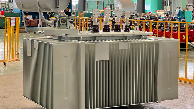
Oil immersed distribution transformers come in two tank configurations. The hermetically sealed (also called fully sealed) type has a welded-shut steel tank with no contact between the oil and outside air. A gas cushion — usually nitrogen, or simply dry air — sits above the oil and absorbs thermal expansion. Because no atmospheric oxygen or moisture ever reaches the oil, the insulation system stays cleaner for longer, and there is no silica gel breather to service.
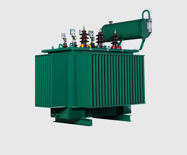
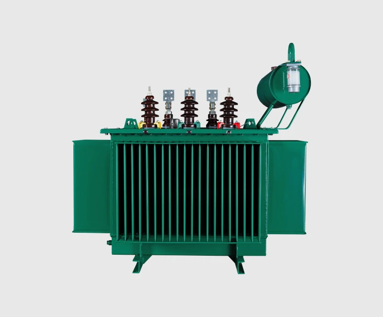
The conservator type uses a separate expansion vessel mounted above the main tank. As the oil heats and expands, it flows up into the conservator; as it cools, oil flows back down. A breather filled with silica gel dries any air entering the conservator. This design handles much larger oil volume changes, which is why it is preferred for power transformers and larger distribution units. The trade-off is that the breather needs periodic silica gel replacement.
For most pad-installed distribution applications between 30 kVA and 2,500 kVA, the hermetically sealed type is the simpler choice. Above that, conservator type becomes more common.

Cooling Methods — ONAN, ONAF, and OFAF
Oil immersed transformer cooling is classified using a four-letter code defined in IEC 60076-2. The first two letters describe the internal cooling medium and its circulation (Oil Natural or Oil Forced); the last two describe the external cooling medium and its circulation (Air Natural, Air Forced, or Water Forced).
• ONAN — Oil Natural, Air Natural. The most common cooling method for distribution transformers. Oil circulates by thermosiphon convection; ambient air cools the radiators without any fans. This is what most people mean by a self-cooled oil immersed transformer.
• ONAF — Oil Natural, Air Forced. Adds cooling fans to the radiators, increasing the continuous rating by roughly 25 to 33 percent over the ONAN value. Useful when peak loading occasionally exceeds the ONAN rating.
• OFAF — Oil Forced, Air Forced. Both an oil pump and radiator fans run continuously. Reserved for larger power transformers where natural convection alone cannot move enough heat.
Most projects in the 30 to 2,500 kVA range use ONAN. ONAF and OFAF become relevant above roughly 5,000 kVA, or where the load profile has sharp peaks the transformer must absorb without oversizing the base rating.
How to Specify an Oil Immersed Transformer
At the quotation stage, you will need to confirm the following parameters. Anything you cannot specify, our engineering team can derive from your single-line diagram and site data.
1. Rated capacity (kVA). Total connected load plus diversity factor plus future headroom. Common standard sizes: 50, 100, 160, 250, 315, 400, 500, 630, 800, 1000, 1250, 1600, 2000, 2500 kVA. Larger units up to 20,000 kVA available.
2. Rated voltages. Both high-voltage (typically 10, 11, 15, 20, 22, 33, or 35 kV) and low-voltage (typically 0.4 kV for industrial and commercial loads, or 11 kV for sub-distribution).
3. Vector group. Dyn11 is the international default for distribution transformers; Yyn0 is also common, particularly in some Asian markets. The vector group affects how the transformer parallels with the existing grid and how it handles unbalanced loads.
4. Tap range. ±5% in two steps of 2.5% is standard for off-circuit tap changing. On-load tap changers are available where voltage regulation is needed under load.
5. Cooling method. ONAN for most applications; ONAF if peak loading approaches rated capacity.
6. Frequency. 50 Hz (most of the world) or 60 Hz (North America, parts of Latin America, some Asian markets).
7. Site conditions. Altitude above 1,000 m requires derating. Coastal, humid, or chemically aggressive environments may need an anti-corrosion finish (special code C) or tropics design (T or H).
Oil Immersed vs Dry-Type Transformer
The choice between oil immersed and dry-type comes down to installation environment and safety code requirements.
Oil immersed transformers handle higher voltages more easily, dissipate heat better, are smaller and lighter per kVA, and cost less per kVA — particularly above 1,000 kVA. They are the standard choice for outdoor pad installations, utility substations, and large industrial sites.
Dry-type transformers eliminate the fire risk associated with mineral oil and have no liquid to leak, which makes them required by many building codes for indoor installations in commercial buildings, hospitals, data centers, and high-rise residential. They cost more per kVA, are larger and heavier for a given rating, and become less common above about 5,000 kVA at distribution voltage levels.
If your installation is outdoors or in a dedicated transformer room with proper containment, an oil immersed unit is usually the more economical choice. If it must sit inside an occupied building without dedicated containment, dry-type is generally required.
Maintenance and Service Life
An oil immersed transformer is mostly a sealed, passive piece of equipment, but a small amount of routine attention extends its life considerably. The basic maintenance items are:
• Annual oil dielectric strength test and moisture content check.
• Visual inspection of tank, radiators, bushings, and gaskets for oil leaks.
• Silica gel breather inspection (conservator type only) and replacement when the indicator color changes.
• Periodic infrared scan of bushing terminations and tap changer contacts to catch hot spots before they fail.
• Dissolved gas analysis (DGA) every one to three years for transformers in critical service.
With basic care, a well-built oil immersed distribution transformer reliably delivers 25 to 30 years of service. Premature failures are almost always traceable to one of three causes: sustained overloading beyond the rated capacity, moisture ingress from a failed breather or gasket, or external short-circuit faults that pass through inadequately protected by upstream relaying.