search
Search

Enter keywords to search for products, blog posts, and more.

English
oil immersed
transformer

Pole Mounted Transformer

Pole Mounted Distribution Transformers — 10kVA to 500kVA

Pole Mounted Distribution Transformers — 10kVA to 500kVA

Single-Phase Pole Transformer Three-Phase Pole Transformer PMT Hermetically Sealed ONAN Self-Cooled 11kV / 22kV / 33kV 50Hz / 60Hz IEC 60076

EverWins manufactures pole mounted distribution transformers in both single-phase and three-phase configurations, with rated input voltages from 6kV to 33kV and capacities from 10 kVA to 500 kVA. These units are designed for overhead utility distribution — mounted directly on wood or concrete poles, on steel platforms, or in H-frame configurations between two poles. Every unit ships hermetically sealed in a welded steel tank, filled with mineral insulating oil, and rated for outdoor service with no scheduled oil maintenance. We build to IEC 60076 and GB/T 1094 as standard, with IEEE C57.12.20 configurations available for North American utility applications.


Service & Delivery

• MOQ: 1 unit for standard configurations

• Lead time: confirmed at quotation, based on capacity, voltage class, and mounting configuration

• Shipping: FOB, CIF, or DDP terms supported; export-grade packaging for sea shipment

• Custom support: single-line diagram review, drawing approval, factory acceptance test (FAT) witness available

• After-sales: technical support via email, phone, or video call; English-speaking engineering team

• Warranty: standard manufacturer warranty as detailed in commercial offer

Specifications

ParameterSpecification
Rated Input Voltage (HV)6 / 10 / 11 / 15 / 20 / 22 / 33 kV
Rated Output Voltage (LV)0.23 / 0.4 / 0.48 kV; 240/120 V split-phase for North American single-phase
Rated Capacity — Single-Phase10 / 15 / 25 / 37.5 / 50 / 75 / 100 / 167 / 200 / 250 / 333 / 500 kVA
Rated Capacity — Three-Phase30 to 500 kVA standard; up to 1,000 kVA on H-frame mount
PhaseSingle-phase or three-phase
Frequency50 Hz or 60 Hz
Winding Connection — Single-PhaseIi0 (primary and secondary in phase)
Winding Connection — Three-PhaseDyn11 or Yyn0 (others on request)
HV Tapping Range±5% or ±2 × 2.5% (off-circuit, no-load)
Cooling MethodONAN (oil natural, air natural)
Winding MaterialCopper or aluminum
Core MaterialCold-rolled grain-oriented silicon steel
Coil StructureToroidal or round, per design optimization
Tank ConstructionHermetically sealed, welded steel
Mounting ConfigurationDirect pole mount with brackets; platform mount; H-frame mount between two poles
Enclosure ProtectionIP65 standard; IP66 available
BushingsPorcelain or polymer; HV and LV; wildlife/animal guards on request
StandardsIEC 60076; GB/T 1094; IEEE C57.12.20 (North American configurations) on request
Ambient Temperature−25 °C to +40 °C (special designs for hotter or colder climates)
Altitude≤ 1,000 m standard; derating available for higher altitudes


Pole Mounted Transformer Product Range


Hermetically Sealed Construction and Engineering

Pole mounted transformers face the toughest service conditions in the distribution network — direct sun, rain, wind, dust, temperature swings of 60 °C or more, lightning, and animal contact. Every unit ships in a fully welded, hermetically sealed steel tank with no breathing connection to the atmosphere, so moisture never reaches the oil over the service life. The core uses cold-rolled grain-oriented silicon steel for low no-load loss, and the windings are wound with copper or aluminum on toroidal or round formers. Bushings are sized for the highest BIL (basic insulation level) appropriate to the rated voltage. Mounting brackets, lifting lugs, and grounding points are positioned per the utility's pole-line standards.

• Hermetically sealed welded steel tank, no breather required

• Cold-rolled grain-oriented silicon steel core for low no-load loss

• Toroidal or round coil structure per design optimization

• Copper or aluminum winding, selectable per order

• BIL-rated porcelain or polymer bushings, HV and LV

• Mounting brackets, lifting lugs, and grounding points to project specification


Full Testing Before Shipment

Every pole mounted transformer is routine tested at our factory before it ships. Tests follow IEC 60076-1 routine test sequence: turns ratio, winding resistance, insulation resistance, no-load loss, load loss, induced overvoltage withstand, and applied voltage withstand. For projects requiring it, we also run lightning impulse tests, short-circuit withstand tests, and temperature rise tests. Hermetic seal integrity is verified with a pressure or vacuum test before oil filling. All routine test data is documented and included with the shipment in a factory acceptance test (FAT) report. Customers may witness the FAT in person or by live video link.


Configured to Your Distribution Network

Overhead distribution practice varies widely by country. North American utility networks favor single-phase pole mounted units with 240/120 V split-phase secondaries and ANSI/IEEE bushing arrangements. European and Asian networks more often use three-phase 11 kV/0.4 kV pole mounted units with IEC bushing patterns. Tropical and coastal sites require enhanced anti-corrosion finishing and animal-protection guards. We configure each order to the specific distribution standard — bushing arrangement, mounting bracket pattern, vector group, surge arrester provisions, secondary terminal layout, and external paint or coating system. Tell us the utility specification your project must meet; we build to it.

More About everwins

EverWins is a transformer, switchgear and substation manufacturer based in Guangdong, China. With 30 years in the power transmission and distribution industry and a 70,000m² production facility, we supply factory-direct to projects in over 30 countries.

About Us Certifications Solutions

FAQs

What is a pole mounted transformer (PMT)?

What is the difference between single-phase and three-phase pole mounted transformers?

A pole mounted transformer, often abbreviated PMT and sometimes called a pole top transformer or power pole transformer, is a distribution transformer designed for installation directly on an overhead utility pole rather than on a concrete pad. It receives medium-voltage power from the overhead primary line (typically 6 to 33 kV) and steps it down to a lower distribution voltage (typically 0.23 to 0.48 kV) for nearby residential, commercial, or small industrial loads. Pole mounted transformers are hermetically sealed, oil-immersed, ONAN-cooled, and built to operate outdoors with no scheduled oil maintenance for the full service life.

How do I select the right kVA capacity for a pole mounted transformer?

Single-phase pole mounted transformers have one HV and one or two LV bushings, and serve loads that need only single-phase electricity — primarily residential lighting, plug loads, and small motors. They are common in North American suburban networks at sizes from 10 kVA up to 167 kVA, often supplying a few houses each. Three-phase pole mounted transformers have three HV and four LV bushings and provide three-phase service for commercial buildings, larger motors, and three-phase industrial equipment. They are typically larger — 30 to 500 kVA on a standard pole, up to 1,000 kVA on H-frame — and more common in European, Asian, African, and Latin American networks. Both are oil-immersed and hermetically sealed; the construction differs only in the number of phases and the corresponding bushing arrangement.

What surge and overcurrent protection comes with a pole mounted transformer?

Capacity is determined by your maximum simultaneous load, multiplied by a diversity factor reflecting how many consumers draw peak power at the same time, with a margin added for future growth. For a typical North American residential service feeding 4 to 8 homes, 25 to 50 kVA single-phase is common. For a small commercial building, 75 to 167 kVA single-phase or 100 to 250 kVA three-phase is typical. For larger commercial or light industrial loads, 250 to 500 kVA three-phase is normal. Always check the rated voltage and frequency required by the connecting utility, and confirm the primary voltage matches the overhead line. Send us your load schedule and we will recommend a capacity.

What is the typical service life of a pole mounted transformer?

The transformer itself includes the BIL-rated bushings that withstand the impulse voltage levels per IEC 60076-3 or IEEE C57.12.20. Lightning surge arresters and fuse cutouts are normally provided as separate pole-mounted accessories, sized to the transformer's BIL and rated current, and installed on the same cross-arm or directly above. We can supply these accessories as a kit with the transformer on request, including polymer surge arresters and dropout fuse cutouts. Wildlife protection covers — bushing boots, animal guards on the cross-arm — are also available where required by utility specification.

Pole Mounted Transformer: Technical Guide

How a Pole Mounted Transformer Works

A pole mounted transformer operates on the same electromagnetic induction principle as any other transformer. Medium-voltage power on the overhead primary line — typically 11, 22, or 33 kV — feeds into the HV bushing and across the primary winding wound on a silicon steel core. The alternating current generates magnetic flux in the core, which induces a lower voltage in the secondary winding, available at the LV bushings for connection to the consumer service drop.

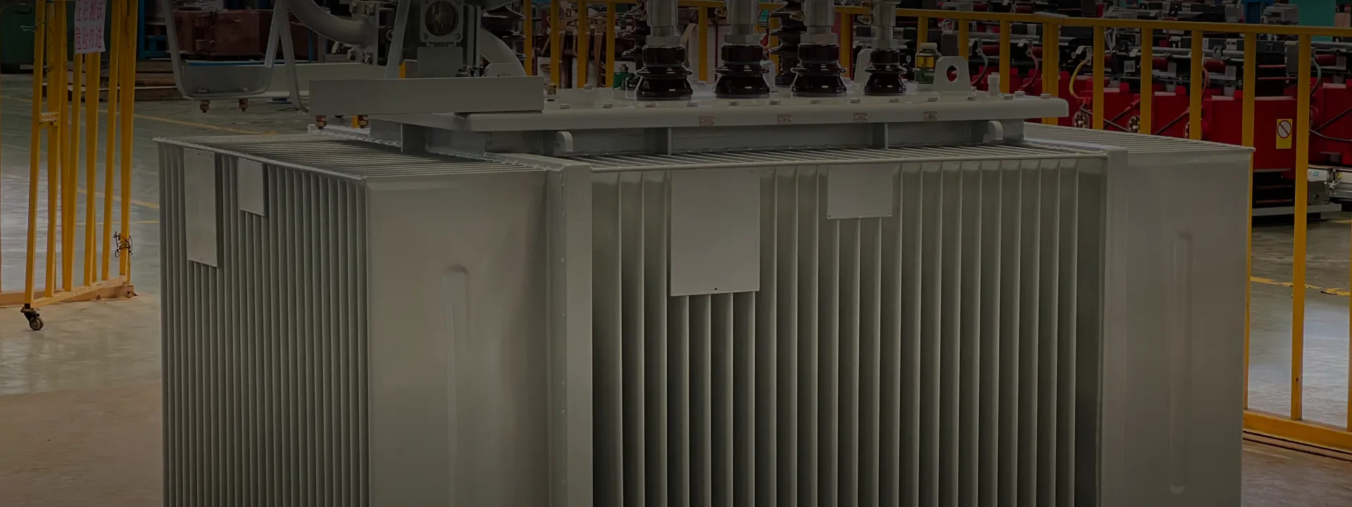
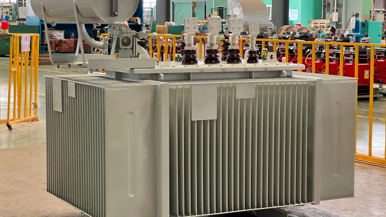
What makes a pole mounted transformer specifically suited to overhead distribution is its compact, sealed construction. The entire core-and-coil assembly sits inside a welded steel tank filled with mineral insulating oil. The tank has no breather and never opens to the atmosphere, so the oil stays clean throughout the unit's service life. Mounting brackets are welded directly to the tank for attachment to the pole, eliminating the foundation work required for a pad-mounted unit. ONAN cooling — heat carried by oil convection from windings to tank wall, then released to ambient air — handles full load with no fans or pumps, which means no auxiliary power and no moving parts to fail.

Single-Phase vs Three-Phase Pole Mounted Configurations

Pole mounted transformers come in two electrical configurations matched to the distribution network they connect to.

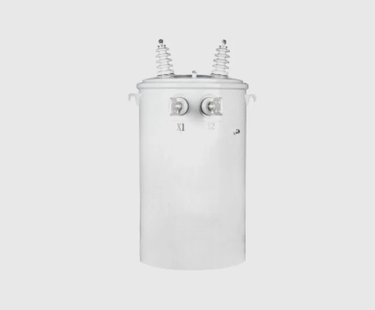
Single-phase pole mounted transformers are the standard for residential overhead distribution in North America and a growing choice in parts of Asia, Africa, and Latin America where extending three-phase service is uneconomical. The primary winding connects either line-to-ground (with one HV bushing) on a wye-connected primary system, or line-to-line (with two HV bushings) on a delta-connected primary. The secondary is typically split-phase 240/120 V for North American applications or 230 V for international markets, feeding several houses through individual service drops. Capacities run from 10 kVA up to 500 kVA, with 25, 37.5, 50, 100, and 167 kVA being the most common sizes.

Three-phase pole mounted transformers supply commercial buildings, three-phase motor loads, and rural networks where three-phase service has been extended to the consumer. The primary side has three HV bushings, connected to all three overhead primary conductors. The secondary side has four LV bushings — three phases plus neutral — supplying three-phase loads at 0.4 kV (50 Hz markets) or 0.48 kV (60 Hz markets). Standard vector group is Dyn11; Yyn0 is also common. Standard pole platform mounting supports capacities up to 500 kVA; H-frame mounting between two poles extends the capacity range to 1,000 kVA.

Mounting Methods — Direct Pole, Platform, and H-Frame

Pole mounted transformers attach to the pole in one of three ways, chosen by transformer weight and the utility's standard pole-line construction.

Direct pole mount — the most common method. The transformer is bolted directly to the pole using a pair of mounting brackets welded to the tank, with bolts or banding straps clamping the unit against the pole. Suitable for single-phase units up to about 100 kVA, and small three-phase units up to about 75 kVA. Quickest installation; no separate platform required.

Platform mount — a horizontal steel platform is attached to the pole below the cross-arm, with the transformer bolted to the platform. Used for larger single-phase units (up to 500 kVA) and three-phase units up to roughly 500 kVA. Provides a stable base for heavier units and easier access for surge arresters and fuse cutouts.

H-frame mount — two parallel poles are connected by horizontal cross-members, with the transformer mounted between them. Used for the largest three-phase pole mounted units (up to 1,000 kVA) and where ground clearance or stability requirements exceed what a single pole can provide. More expensive than single-pole mounting but distributes the weight across two structures.

Protection — Surge Arresters, Fuses, and Wildlife Guards

A pole mounted transformer is exposed to lightning strikes, switching surges, and direct contact from birds and small animals. Three categories of accessory protect the transformer and the network.

Lightning surge arresters are installed on the cross-arm next to each HV bushing. When an overvoltage surge appears on the primary line, the arrester conducts the surge current to ground before it can damage the transformer's insulation. Arresters are sized to the system's BIL (basic insulation level) and to the maximum continuous operating voltage of the network. Polymer-housed arresters have replaced porcelain in most new installations.

Fuse cutouts — sometimes called dropout fuses or expulsion fuses — provide short-circuit protection on the HV side. A fault on the secondary side or inside the transformer pulls high current through the fuse element, which melts and physically drops the fuse holder open, visibly isolating the faulty transformer from the network. The dropped fuse is easy to spot from the ground, simplifying utility patrol and replacement.

Wildlife guards — bushing boots, animal-shield disks, and cross-arm covers — prevent birds and squirrels from bridging energized terminals to ground or to other phases. Wildlife contact is a leading cause of distribution-line outages in many regions; basic guards are inexpensive insurance against repeat faults at the same pole.

How to Specify a Pole Mounted Transformer

At the quotation stage, confirm the following parameters. Anything you cannot specify, our engineering team can derive from your single-line diagram and utility specification.

1. Phase configuration. Single-phase for residential and small commercial loads; three-phase for commercial buildings, three-phase motors, and larger services.

2. Rated capacity (kVA). Total connected load × diversity factor + future growth allowance.

3. Rated voltages. Primary (commonly 11, 22, or 33 kV on 50 Hz systems; 7.2, 12.47, or 24.94 kV on 60 Hz systems) and secondary (commonly 0.4 kV for three-phase, 240/120 V split-phase for single-phase North American).

4. Vector group (three-phase only). Dyn11 is the international default; Yyn0 is also common.

5. Tap range. ±5% in two steps of 2.5% is standard for off-circuit tap changing.

6. Bushing arrangement. IEC pattern for 50 Hz networks; ANSI/IEEE pattern for North American 60 Hz networks.

7. Mounting method. Direct pole mount for smaller units; platform mount for medium; H-frame for largest three-phase units.

8. Accessories. Lightning surge arresters, fuse cutouts, wildlife guards, secondary terminal box, secondary breaker — supplied as part of a complete kit on request.

9. Site conditions. Altitude (derating above 1,000 m), coastal/tropical environment (enhanced anti-corrosion paint), extreme temperature range, pollution level.

Maintenance and Service Life

A hermetically sealed pole mounted transformer is one of the lowest-maintenance pieces of equipment in a utility distribution network. Because the tank never breathes, there is no oil sampling routine, no breather to service, and no gaskets that age. Maintenance reduces to:

• Visual inspection during pole-line patrol — check for oil leaks at bushings, physical damage to tank, missing or damaged surge arresters, and wildlife contact damage.

• Infrared thermography — periodic thermal scan to identify hot bushing terminations, loose connections, or overloaded units.

• Surge arrester inspection — confirm arresters have not failed (visible disk discoloration on polymer types).

• Bushing cleaning — wipe contamination from porcelain bushings in heavy-pollution environments to prevent flashover.

• Replacement of failed fuse cutouts after fault clearing.

With this basic patrol routine, a properly specified pole mounted transformer reliably delivers 25 to 30 years of service. Premature failures are almost always traceable to one of three causes: sustained overloading from undersized initial capacity, lightning damage from missing or undersized surge arresters, or tank corrosion in unprotected coastal and tropical environments.