Metal-Clad Switchgear: Technical Guide
What Metal-Clad Switchgear Is — The Standards Definition
Metal-clad is a specific construction class within the broader category of metal-enclosed medium voltage switchgear. The defining standards — IEEE C37.20.2 (North American) and IEC 62271-200 (international) — both list the same four mandatory features that distinguish metal-clad from other metal-enclosed designs. First, the main switching device must be a removable (withdrawable) circuit breaker. Second, the major components — main bus, circuit breaker, and cable terminations — must each occupy a separate compartment surrounded by grounded metal barriers. Third, automatic shutters must cover the stationary primary contacts whenever the breaker is racked out, so no operator can contact a live primary terminal. Fourth, the instrument transformers and control wiring must be isolated from the primary power circuits by a grounded metal barrier.
These four requirements together produce a switchgear that contains internal faults to a single compartment, protects operators from accidental contact with energized parts, and allows in-service maintenance of one cubicle while the rest of the line-up stays in operation. A switchgear cabinet with a fixed-mounted breaker, or with non-compartmented construction, is metal-enclosed but is not metal-clad — an important distinction at procurement stage, because metal-clad is required by many utility and industrial specifications for primary distribution at 5 kV and above.
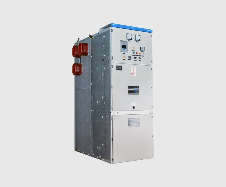
KYN Type Designation — What the Letters Mean
Chinese GB 3906 uses a type designation system that compactly encodes the cubicle's construction class, mounting method, installation environment, and voltage rating. The KYN prefix that appears on every cubicle in our range breaks down as follows:
• K — Kǎizhuāng (铠装), meaning armored or metal-clad. The cubicle meets the four-compartment metal-clad construction class.
• Y — Yídòng (移动), meaning withdrawable or movable. The circuit breaker is mounted on a withdrawable truck.
• N — Nèibù (内部) or indoor. The cubicle is designed for installation in a protected indoor switchroom.
The number that follows the KYN prefix (28, 37, 61, etc.) is the design series, set by the standardization body. The number after the hyphen is the rated voltage class — KYN28-12 is a 12 kV cubicle of design series 28; KYN61-40.5 is a 40.5 kV cubicle of design series 61. The Chinese KYN designation maps directly onto the IEC 62271-200 description: KYN-type cubicles are LSC2B-PM service-continuity category with metal partitions between compartments, the same construction class as Western-named products like the metal-clad ranges from major European and North American manufacturers.
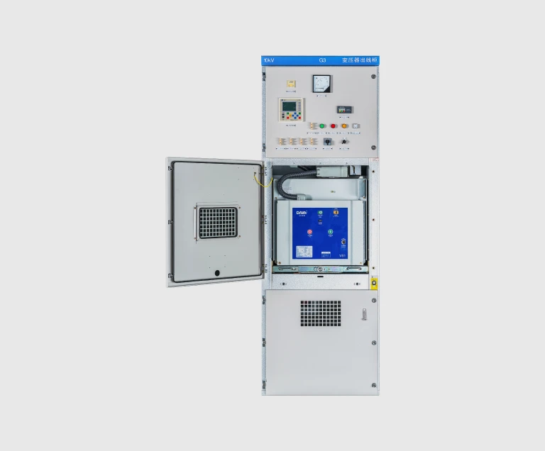
The Four Compartments of Metal-Clad Switchgear
A KYN cubicle is physically divided into four electrically and mechanically separated compartments. The separation matters because it limits the impact of any internal fault to a single compartment rather than letting it propagate across the entire cubicle.
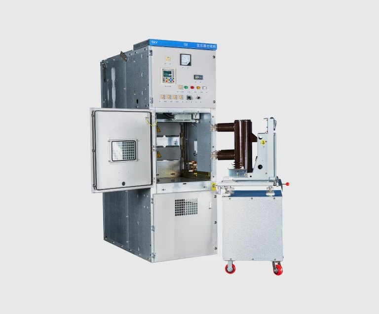
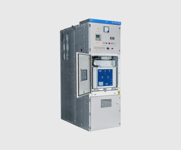
• Circuit breaker compartment — houses the withdrawable VCB truck. Accessed from the front through a hinged door interlocked with the breaker position. The compartment includes the truck rails, primary disconnect contacts with auto-shutters, secondary control plug, and racking mechanism.
• Main busbar compartment — sits above the breaker compartment and runs the full length of the switchboard line-up. Contains the three-phase main busbars supported on epoxy insulators. Top-mounted to keep the most critical conductors furthest from operator access points.
• Cable compartment — at the rear of the cubicle, houses the cable terminations, current transformers, lightning arresters (when fitted), and the earthing switch. Accessed from the rear through an interlocked door for cable installation and maintenance.
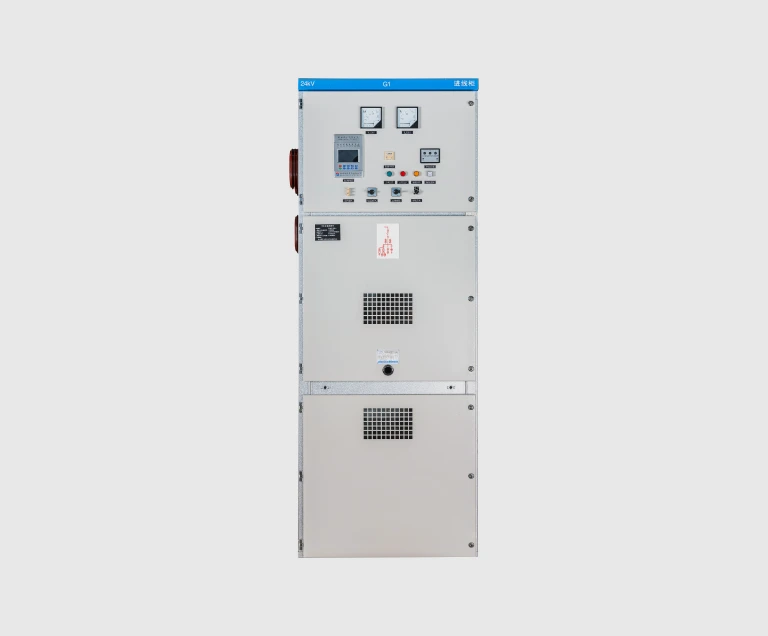
• Low-voltage compartment — at the top front of the cubicle, contains the protective relays, control switches, indicating lights, meters, and terminal blocks. Completely isolated from the primary compartments by a metal barrier; can be safely accessed with the cubicle live for relay testing and metering.
Vacuum Circuit Breaker vs SF6 Circuit Breaker
Modern metal-clad switchgear uses one of two arc-interruption technologies in the circuit breaker. Both are mature, reliable technologies; the choice between them is driven by voltage class, environmental considerations, and local market preference.
Vacuum circuit breakers interrupt the arc by drawing it across contacts separated inside a sealed vacuum bottle. With no gas molecules to ionize, the arc extinguishes almost immediately at the next current zero crossing. Vacuum bottles are essentially maintenance-free over their service life of around 30,000 mechanical operations, contain no greenhouse gas, and have no end-of-life disposal issues. They are the dominant technology for 12 kV through 40.5 kV switchgear globally.
SF6 circuit breakers interrupt the arc inside a chamber pressurized with sulfur hexafluoride gas, which has excellent dielectric and arc-quenching properties. SF6 remains common for the highest voltage classes (above 72.5 kV) and in some ring main unit (RMU) designs. The trade-off is that SF6 is a potent greenhouse gas — roughly 24,000 times the warming potential of CO₂ — and is subject to growing regulatory restriction. New IEC standards now require leak monitoring and end-of-life recovery.
EverWins uses vacuum circuit breakers as the standard interrupter in the KYN range, in line with international market practice and the regulatory direction on fluorinated gases.
Internal Arc Classification (IAC) and Service Continuity (LSC)
IEC 62271-200 classifies metal-enclosed switchgear by two characteristics that matter for safety and operability.
Service Continuity (LSC) describes how much of the switchboard stays in operation when one cubicle is opened for maintenance. LSC1 means the whole switchboard must be de-energized. LSC2A means the affected functional unit and the main bus can stay in service. LSC2B is the highest level — the main bus, the adjacent cubicles, and the cable compartment of the affected cubicle all remain in service while the breaker compartment is open. KYN-type cubicles are LSC2B-PM (with metal partitions), the strictest service-continuity category.
Internal Arc Classification (IAC) describes how the cubicle behaves if an internal arcing fault occurs. IAC-classified cubicles are tested to a specified short-circuit current for a specified duration (typically 16 kA / 1 s through 50 kA / 1 s, depending on the design) and must contain the arc and direct overpressure venting upward — away from operators standing in front of, beside, or behind the cubicle. The full IAC class designation (e.g. IAC AFLR 25 kA 1 s) specifies which sides of the cubicle are accessible to operators: A = front, L = lateral (sides), R = rear. AFLR means the cubicle protects operators on all four sides — front, both sides, and rear.
IAC AFLR is available on the EverWins KYN range on request. It is required by an increasing number of utility specifications and is highly recommended for any indoor switchroom where operators routinely move around the switchboard.
How to Specify Metal-Clad Switchgear
At the quotation stage, confirm the following parameters. Anything you cannot specify, our engineering team can derive from your single-line diagram and protection schedule.
1. Rated voltage. 12 kV class for 10/11 kV systems, 24 kV class for 20/22 kV systems, 40.5 kV class for 33/35 kV systems.
2. Rated main busbar current. Set by the largest continuous load on the bus, with a margin for future growth. Common values: 630 A, 1250 A, 1600 A; higher available on request.
3. Rated short-circuit current. From your system fault-level study. The cubicle short-time withstand must equal or exceed the prospective fault current at the switchboard location. Common values: 25 kA, 31.5 kA, 40 kA, all for 4 seconds.
4. Number and function of cubicles. List each cubicle by function: incoming feeder, outgoing feeder, transformer, motor, capacitor bank, voltage transformer, bus coupler, bus section, metering. The single-line diagram defines this.
5. Protection scheme. The relay configuration on each cubicle: overcurrent and earth fault on outgoing feeders, transformer differential and Buchholz trip on transformer feeders, motor protection on motor feeders, distance or directional protection on incoming feeders where required.
6. Cable entry direction. Bottom entry (most common) or top entry, with the cable trench or tray dimensions confirmed.
7. Internal arc class. IAC AFLR is recommended where operators routinely move around the switchboard.
8. Auxiliary supplies. Control voltage (typically 110 V DC, 220 V DC, or 220 V AC), trip and close coil voltages, and the source of these supplies.
Installation and Maintenance
Metal-clad switchgear is among the longest-lived equipment in a substation, with a typical service life of 30 to 40 years when the routine maintenance is kept up. The dominant maintenance items are:
• Annual visual and operational inspection — verify interlock chains, racking mechanism, shutter operation, and ground continuity.
• Three-yearly contact resistance measurement — check primary disconnect and earthing switch contacts; a rising contact resistance indicates fretting or oxidation.
• Three- to five-yearly vacuum integrity test on the breaker bottles — confirms the interrupters still hold vacuum and will still interrupt fault current.
• Periodic relay testing — secondary injection of the protective relays at the interval specified by the protection coordination study.
• Visual check of busbar connections during major outages — torque verification on bolted joints, infrared scan of joint temperatures under load.
Properly specified and maintained, a metal-clad switchboard reliably handles two to three generations of facility equipment changes over its service life. The dominant failure modes are insulation degradation in heavily polluted indoor environments, contact failure from undersized cubicles operating near rated current continuously, and interlock failure from physical damage during racking — all preventable through correct specification at order stage and basic maintenance discipline through service life.